Category

BLDC Motor Supplier
Home » High Torque BLDC Motor » 3 kW (4hp) 72V BLDC Motor with Encoder
3 kW (4hp) 72V BLDC Motor with Encoder
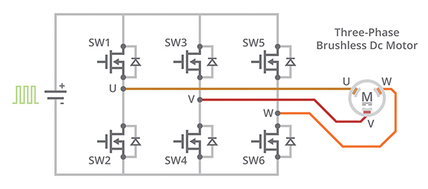
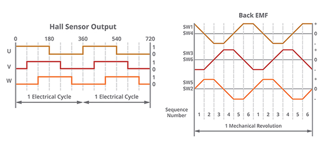
Since the birth of brushless motor, Hall effect sensor has always been the main force of realizing commutation feedback. Because three-phase control only requires three sensors and the unit cost is rather low, simply from the perspective of BOM cost, they are usually the most economic selection of realizing commutation. Motor stator is embedded with Hall effect sensor inspecting the rotor position, the transistor in three-phase bridge can be switched to drive the motor. The three Hall effect sensor outputs are usually marked with U, V and W channels. Although Hall effect sensor can effectively solve the BLDC motor commutation problem, they can only satisfy half demands of the BLDC system.

3 kW (4hp) 72V BLDC motor with encoder specification


Although Hall effecto sensor can drive BLDC motor by the motor controller, it's a pity that it can only control the speed and direction. In the three-phase motor, Hall effect sensor can only provide the angle position in every electric circulation. As the quantity of magnetic pole pairs increases, the quantity of the electrical circulations for each mechanical rotation increases accordingly. Moreover, as BLDC application becomes more popular, the demand on precision position sensing increases accordingly. To ensure the stable and complete solution, BLDC system should provide real-time position information, so that controller can not only trace the speed and direction, but also track the journey distance and angle position.
In order to satisfy the demand to a more strict position information, the common solution is to add incremental rotary encoder to high torque BLDC motor. Generally speaking, in addition to Hall effect sensor, incremental encoder will also be added into the same control feedback loop system, wherein, Hall effect sensor is used for motor commutation, while encoder is used to trace the position, revolution, speed and direction more accurately. Since Hall effect sensor can only provide new position information when each Hall state changes, its precision can only reach six states of every electrical circulation. However, as to the bipolar motor, it only has six states for each mechanical circulation. Compared with the incremental encoder which can provide the resolution ratio, it is obvious that the two are required.
 However, since motor manufacturers must install both Hall effect sensor and incremental encoder on their motors, many encoder manufacturers start to provide the incremental encoder with commutation output, which is usually named as the commutator encoder in short. These encoders are designed specially, so that they can not only provide the traditional orthogonal A and B channels(and the index impulse channel Z of "revolving for one time" under some conditions), but also provide the standard U, V and W commutation signals required by most BLDC motor drivers. In this way, the motor designer can save the unnecessary procedures of installing Hall effect sensor and incremental encoder simultaneously.
Although the strengths of this method are obvious to all, this method has been compromised greatly. Just as the previous text indicates, to ensure the effective commutation of BLDC motor, the positions of the rotor and stator must be mastered. It means that the U/V/W channels of the commutator encoder must be correctly aligned with the phases of BLDC motor.
Customize a BLDC motor with encoder or with brake, please feel free to contact us.

3 kW (4hp) 72V BLDC motor with encoder specification

Model: ATO-130WDM10030
Matched Controller Model: ATO-TH-G
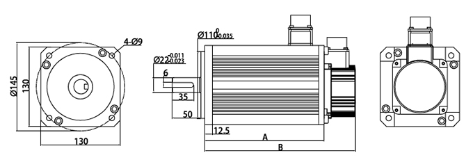
Square Flange Size: 130 mm
Rated Voltage: 72V DC
Rated Current: 51.3 A
Rated Power: 3 kW
Maximum Power: 9.4 kW
Holding Torque: 10 Nm
Peak Torque: 30 Nm
Rated Speed: 3000 rpm
Maximum Speed: 3600 rpm
Electric Potential: 20 V/Krpm

Although Hall effecto sensor can drive BLDC motor by the motor controller, it's a pity that it can only control the speed and direction. In the three-phase motor, Hall effect sensor can only provide the angle position in every electric circulation. As the quantity of magnetic pole pairs increases, the quantity of the electrical circulations for each mechanical rotation increases accordingly. Moreover, as BLDC application becomes more popular, the demand on precision position sensing increases accordingly. To ensure the stable and complete solution, BLDC system should provide real-time position information, so that controller can not only trace the speed and direction, but also track the journey distance and angle position.
In order to satisfy the demand to a more strict position information, the common solution is to add incremental rotary encoder to high torque BLDC motor. Generally speaking, in addition to Hall effect sensor, incremental encoder will also be added into the same control feedback loop system, wherein, Hall effect sensor is used for motor commutation, while encoder is used to trace the position, revolution, speed and direction more accurately. Since Hall effect sensor can only provide new position information when each Hall state changes, its precision can only reach six states of every electrical circulation. However, as to the bipolar motor, it only has six states for each mechanical circulation. Compared with the incremental encoder which can provide the resolution ratio, it is obvious that the two are required.

Although the strengths of this method are obvious to all, this method has been compromised greatly. Just as the previous text indicates, to ensure the effective commutation of BLDC motor, the positions of the rotor and stator must be mastered. It means that the U/V/W channels of the commutator encoder must be correctly aligned with the phases of BLDC motor.
Customize a BLDC motor with encoder or with brake, please feel free to contact us.
Post a Comment:
You may also like:

