Category

BLDC Motor Supplier
Home » BLDC Motor Wiki
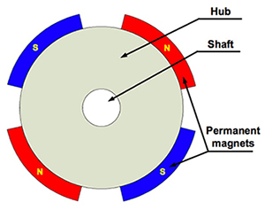
By reversing the electric motor settings, the BLDC motor overcomes requirements of the mechanical commutator. The winding becomes the stator, while the permanent magnet turns into a part of the rotor. The stator is usually made up of the steel plates. The axial-direction notching can include an even number of windings along its internal margin. The rotor is made up of one axis and one hub with the permanent magnet. The permanent magnet is aligned between two pairs to eight pairs of magnetic poles, and alternates between "N" and "S." Fig. 2 shows configurations of one commonly-seen magnetic iron. Under the condition, two magnetic irons can be directly connected to the rotor's hub.


The brushless DC motor adopts electronic commutation, with the coil remaining motionless and the magnetic poles rotating. The position of the magnetic poles of the permanent magnet is perceived by Hall elements. According to the perception, the electronic circuits are adopted, and the current direction in the coil is changed at an opportune time, which can ensure generation of the magnetic force in the correct direction to drive the electric motor. This is an effective way to address defects existing in brushed motors.
Torque is an important parameter of the electric motor test. In the electric motor efficiency evaluation, torque is an indispensable variable to be measured, and the accuracy of the torque measurement is directly linked to the accuracy of the electric motor’s efficiency test. When the transmission method is used to transmit the torque, the physical parameters of electric components will undergo certain degree of changes. The correspondence between the change and the torque can be utilized to measure the torque. According to different physical parameters, transmission can be further divided into the magnetic elastic type, strain type, vibrating wire type, photoelectric type, etc. Currently, the transmission method has found the widest applications in the torque measurement field.
The BLDC Hall sensor have five wires, including the public power source anode of Hall sensor, public power source cathode, A-phase Hall output, B-phase Hall output, and C-phase Hall output. We can make use of the five Hall leads of the BLDC controller (either 60° or 120°) to connect the negative and positive power source on the Hall sensor' lead of the BLDC motor. Connect the lead of the remaining three phase sensors, namely A, B and C, arbitrarily to the Hall signal lead of the controller. Power on the controller, and the controller will provide power for Hall sensor for detection of the BLDC motor.
The brushless DC (BLDC) motor is a type of the synchronous electric motor. In other words, the rotating speed of the electric motor's rotor is subject to the impact of the speed of the stator's rotating magnetic field and the number of the stator's poles (p), namely n=60.f/p. When the number of the stator's poles is fixed, change of the frequency of the stator's rotating magnetic field can change the rotating speed of the stator.


When the vacuum cleaner is working, the motor has too high temperature rise and a charring smell will be generated. In serious conditions, the plastic shell will also be heated. After a long period, the cartridge fuse, or even the motor and shell will be burned, thus causing disasters. Such a fault is usually caused by the overload operation of the motor. The specific reasons usually include the following two points:
In the closed-loop, the current loop can control the average current. In the general double closed-loop design, the detected current is an instant value rather than the average value. Besides, the current increases from zero to certain value after phase shift of the brushless DC motor, when the duty ratio is constant. Even if the electric current loop is added, the current also increases from 0. Because of the electric motor's inductance, there is a minimum for the rise of the current. In some electric motor control, the current is also fluctuating.
Therefore, is it possible to adopt the permanent magnet as the rotor and the electric coil as the stator? If yes, the puzzlement facing exchange of the electric brush can be addressed and the generation of electric sparks can be avoided. In fact, the new-type specialized electric motor, BLDC motor, adopts this structure. The electrification sequence of the coil is controlled, and the coils at the opposite direction are put in the same group. Meanwhile, through galvanization, the magnetic field at the same direction is generated. Take the three-phase BLDC motor for example. The number of the electric motor's pole pairs is three. Every pair of magnetic poles is connected with power according to certain sequence to achieve the effect of rotating the magnetic field. Under the effect of the magnetic field, the permanent magnet's rotor moves in the direction the same to the magnetic field, and will move together with the rotating magnetic field. This means that constant changes of the electrification sequence can ensure the stator to rotate.


Every time the BLDC motor swifts its direction, there is a winding connected to the positive electrode of the power source (the current enters the winding); the second winding is connected with the negative electrode (the current flows out therefrom); and the third winding is at a power-losing state. The torque is generated between the magnetic field and the permanent magnet. Under the ideal state, the torque peak appears at the orthogonality of two magnetic fields, and the torque is the weakest when the two magnetic fields are the weakest. In order to maintain rotation of the motor, the magnetic field generated by the stator's winding should keep on changing the position, because the rotor will rotate in the direction parallel to the stator's magnetic field. The "six-step commutation" defines the sequence of the winding electrification.
To be specific, pulse width modulation (PWM) is an effective method which makes use of digital output to control the artificial circuit, particularly in controlling the motor's rotating speed and largely saving the energy. The PWM has a strong noise immunity, and is space-saving and relatively economic. At present, the analog control circuit has the following defects: The analog circuit can easily flow with the time, thus generating unnecessary heat loss and sensitivity to noises. After the PWM technology is adopted, the above defects can be avoided. The analog signals are controlled in the digital way, which can significantly reduce the cost and power consumption.
The linchpin to BLDC control is identification of the phase-switching moment. From Fig. 1, it can be seen that the middle of every two phase-switching points is corresponding to one point whose back electromotive force polarity is changed. For example, the point in which the back electromotive force changes from positive to negative or from negative to positive is called the zero-crossing-point. Based on the characteristic of the back electromotive force, as long as we can correctly detect the zero-crossing-point of the back electromotive force, we can identify the phase-switching moment by delaying the point by 30°.
Bearing is an important part of BLDC motor operation. Whether the protection and maintenance of bearings are standardized or not directly affects the service life of bearings, and also directly affects the safe and efficient operation of motors. Therefore, it is necessary to do a good job of protection and maintenance on weekdays, according to the fault phenomena, deal with them in time to prevent the expansion of the fault, so as to prevent burning down the motor and causing greater economic losses.

