Category

BLDC Motor Supplier
Home » BLDC Motor Controller
We all know that brushless DC motor with Hall sensor can inspect the Hall position, and the speed will also have an error of around 5%, then can stable speed be realized? Indeed, Hall itself could not realize it. There is a kind of speed stabilizing controller of loop-locked current, which is used to regulate the current, so as to adapt to different load changes, thus maintaining a relatively stable speed. However, it could not guarantee that the speed will never change, instead it only tries to maintain the stable speed.


BLDC Motor Controller Specifications
 Working frequency: 16.6KHz
Standby current: less than 1 mA
5V Sensor Power Current: 40mA
Power supply voltage: 72V and below 72V
Model: ATO-M-BLDC-TH-G
Power supply current: 150 mA
Maximum battery current: adjustable
Continuous Phase Line Current: 60A-200A, depending on the motor model
Brake analog signal and pedal signal input: 0-5V. Three-wire resistance pedal can be used to generate 0-5V signal.
Full power operating temperature range: - 30°C to 90°C, 100°C shutdown (controller shell temperature)
Peak Phase Line Working Current, 10 seconds: 150A-550A, depending on the motor model
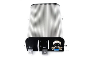
The BLDC motor controller is usually equipped with the following outgoing lines:
1. Electric motor line (Figure 1 in A line): The BLDC motor controller has three lines, namely A, B and C phase line. The yellow line represents A-phase, the blue line represents B-phase, the green line represents C-phase. Of course, there is exception. Thus, the maintenance staff should try to change the sequence of the three lines until the electric motor can operate normally.
2. Power source line (Figure 1 in B line): The electric line of the BLDC motor usually has three wires. The thinner one is the locking line, which can provide 14V and 5V power source for the BLDC motor controller. The other two thick lines (red and black) is responsible for power supply for the power tube.
Brushless DC motor controller of electric vehicle mainly consists of MCU main control circuit, power tube pre-stage drive circuit, electronic commutator, Hall signal detection circuit, switch signal circuit, undercurrent detection circuit, current limiting/overcurrent detection circuit, brake signal circuit, speed limiting circuit, power supply circuit and so on.
Brushless dc motor is one of the commonly used components in the industrial field. Many electrical appliances around us use brushless dc motor to replace the motor with many insuperable defects such as low efficiency and high noise, like three-phase asynchronous motor and stepper motor. In fact, BLDC motor is a kind of synchronous motor, which can control and maintain a certain speed within the rated load range when the load changes, but it must be used together with the brushless motor controller. Why?
The operation speed of the digital signal processor of the ATO BLDC motor controller is relatively fast, which can be used in the motor control system of some complex real-time control algorithms, such as: kalman filter, the state estimate and parameter adaptive control and so on. These complex control method is very good to improve the performance of the motor control system. In addition, the application software program of digital signal processing can be programmed by electroplating assembly language or C language, or both of which can be used to write nested control program, thus providing great convenience for R&D personnel and glucoside in the research and development, debugging and application of motor controller.
Motor controller is an integrated circuit which controls the motor to work by the set direction, speed, angle and response time through active operation. In electric vehicles, the functions of motor controller are to convert the electric energy stored by power battery into the electric energy needed to drive the motor according to the instructions of gear, throttle and brake, so as to control the starting operation, forward and backward speed and climbing force of electric vehicles, or to help brake the electric vehicles and store partial braking energy in power batteries. It's one of key parts of the electric vehicles.

