Category

BLDC Motor Supplier
Home » BLDC Motor Controller » High Power BLDC Motor Controller for Electric Vehicles
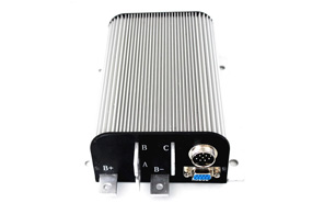
High Power BLDC Motor Controller for Electric Vehicles
BLDC Motor Controller Specifications


- Working frequency: 16.6KHz
- Standby current: less than 1 mA
- 5V Sensor Power Current: 40mA
- Power supply voltage: 72V and below 72V
- Model: ATO-M-BLDC-TH-G
- Power supply current: 150 mA
- Maximum battery current: adjustable
- Continuous Phase Line Current: 60A-200A, depending on the motor model
- Brake analog signal and pedal signal input: 0-5V. Three-wire resistance pedal can be used to generate 0-5V signal.
- Full power operating temperature range: - 30°C to 90°C, 100°C shutdown (controller shell temperature)
- Peak Phase Line Working Current, 10 seconds: 150A-550A, depending on the motor model
- Design for Electric Motorcycle and Electric Scooter
- Powerful and Intelligent Microprocessors
- High Speed and Low Loss Synchronous Rectifier PWM Modulation
- Strict Current Limitation and Torque Control
- Limit battery current to half of the maximum phase current of the controller
- Greater start-up current, faster start-up speed
- Anti-electromagnetic interference, strong anti-vibration performance
- Fault indicator indicates various faults, which is convenient for users to detect and maintain.
- Battery protection function: when the battery voltage is low, alarm and current attenuation will be carried out in time. When the battery voltage is too low, output will be stopped to protect the battery.
- Beautiful and fast heat dissipation aluminium shell with radiator spine
- With over-temperature protection function: when the temperature is too high or too low, the current will be automatically attenuated to protect the controller and battery.
- Hall position sensor compatible with 60 or 120 degrees
- Support any pole number of high power and high torque brushless DC motor
- Up to 40,000 rpm electrical speed. (Electrical speed = actual speed * motor pole logarithm)
- The brake switch is used to control entering regenerative brake.
- 0-5V brake signal used to control regenerative braking strength
- High pedal protection: When the key is opened, the pedal signal will be detected, and if there is a valid signal, it will not be output.
- Three power generation modes: brake switch power generation, release pedal power generation, 0-5V analog signal power generation
- Current doubling: small battery current can achieve larger motor output current
- Easy Installation: Use a 3-wire pedal potentiometer to work
- Fault detection and protection. The fault can be identified by the LED flicker code.
- Real-time monitoring of battery voltage. Battery voltage too high or too low will weaken the output and stop working.
- Built-in current loop and overcurrent protection.
- The controller has the function of temperature measurement and protection.
- The controller has the function of temperature measurement and protection. Current cuts will be made at low and high temperatures to protect controllers and batteries. If the temperature of the controller is higher than 90 C, the current will drop sharply, and the output will be cut off automatically when the temperature reaches 100 C. At low temperatures, the current usually starts to drop at 0 C.
- During power generation, the voltage will always be monitored by the controller. If the voltage is found to be too high, the controller immediately cuts the current until power generation stops.
- The maximum speed of configurable commutation is half of the maximum forward speed.
- The controller can be configured by connecting the serial port of the computer, and the software can be updated. The controller configuration program can run on all Windows versions.
- Provide 5V sensor power supply.
- Three switch inputs. When GND is connected, it is an effective signal. The default is pedal safety switch input (which needs to be configured by client software), brake switch input and commutation switch input.
- Three 0-5V analog inputs. The default is pedal analog signal input, brake analog signal input and motor temperature sensor analog signal input.
- Boost switch can be configured. When the switch is turned on, the controller will output the maximum current it can reach.
- The economy switch can be configured. When the switch is turned on, the maximum driving current of the limiting controller is half of the normal condition.
More specs infomation about this motor controller or buy it online, please feel free to contact us.
Post a Comment:
You may also like:


What is price for this controller?
Thanks