Category

BLDC Motor Supplier
Home » BLDC Motor FAQ » How to Control BLDC Motor using PWM?
How to Control BLDC Motor using PWM?
The BLDC motor has found wide applications in the field of household applications, automobile, medical care, industrial equipment, etc. Meanwhile, the three-phase BLDC motor is more popular than other BLDC motor series. Fig. 1 is the schematic diagram of the driving part of the three-phase BLDC motor, which mainly includes collection of the Hall information, the corresponding modulation made to the three-phase inverter based on Hall signals, the switching sequence of the three-phase inverter PWM and the PWM duty ratio. Different modulation methods have a huge influence on the operation performance of the BLDC motor. In recent years, with refinement of the motor control system, the appearance of the sine PWM can reduce the motor pulse and alleviate the current waveform distortion, but the latter's algorithm is more complex.
 Square wave 120° PWM
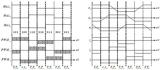
The Hall value (changing for six times in every electric cycle) is used to change the UVW-phase current flow direction. However, the current direction will not change within the same Hall value. At any moment, only the upper bridge of one phase can be conducted with the lower bridge of the other phase. The control mode is simple. However, the torque deflection which can be as large as 60°exists, so the efficiency is thus impaired and the rotating noises might accompany.

Sine Pulse Width Modulator (SPWM)
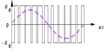
The DC voltage imposed on the MOS tube can constitute the equivalent sine voltage via the switching control of PWM. Since the neutral point is zero, the phase voltage of the electric motor is also sine. In this way, the electric motor's phase current also follows the sine changing rules, thus eliminating the torque fluctuations. According to the area equivalence principle, the sine wave can be equivalent to the PWM wave. As shown in figure, this method allows to constantly regulate the PWM duty ratio to realize the sine voltage effect.
 The value of ωt should be known before SPWM. However, we can just obtain the general information of six positions, including 60°, 120°, 180°, 240°and 360°, from Hall elements. This necessitates our inference of the internal angle of 60° according to the interval of the previous Hall value changes. When the electric motor is static, it is impossible for us to infer the internal angle information. We still need to adopt the wave form 120°PWM to start the electric motor. However, after the BLDC motor obtains a steady rotation, we can infer the internal angle and exchange to the SPWM mode.
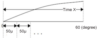
Method to infer the internal angle: As shown in the figure, the time required by every 60°is calculated, divide it by the time of PWM cycle to work out the increase of the internal angle following increase of one PWM within 60°. Then add the increase to the maximum angle of Hall to obtain the current angle. The UVM three phases are apart from each other by 120°.


The Hall value (changing for six times in every electric cycle) is used to change the UVW-phase current flow direction. However, the current direction will not change within the same Hall value. At any moment, only the upper bridge of one phase can be conducted with the lower bridge of the other phase. The control mode is simple. However, the torque deflection which can be as large as 60°exists, so the efficiency is thus impaired and the rotating noises might accompany.

The DC voltage imposed on the MOS tube can constitute the equivalent sine voltage via the switching control of PWM. Since the neutral point is zero, the phase voltage of the electric motor is also sine. In this way, the electric motor's phase current also follows the sine changing rules, thus eliminating the torque fluctuations. According to the area equivalence principle, the sine wave can be equivalent to the PWM wave. As shown in figure, this method allows to constantly regulate the PWM duty ratio to realize the sine voltage effect.

Method to infer the internal angle: As shown in the figure, the time required by every 60°is calculated, divide it by the time of PWM cycle to work out the increase of the internal angle following increase of one PWM within 60°. Then add the increase to the maximum angle of Hall to obtain the current angle. The UVM three phases are apart from each other by 120°.

Post a Comment:
You may also like:

