Category

BLDC Motor Supplier
Home » BLDC Motor FAQ » How to Wire Brushless DC Motor with Controller?
How to Wire Brushless DC Motor with Controller?
The BLDC electric motor replaces the mechanical brush and the mechanical commutator through the electronic redirector, which can maintain advantages of the brushed motor and eliminate the "chronic problems" of the electric brush and commutator. The BLDC motor features a simple structure, reliable performance, high efficiency, and convenient maintenance.

The BLDC motor includes the stator and the rotor. The stator includes the iron core and the coil winding. The iron core includes the yoke of the centric hole and the gear part evenly distributed in the peripheral of the yoke. The gear part is externally set up with the teeth top. The coil winding includes the wire wrapping package on every gear part. Between every two adjacent gear parts, there should be a notch which can tolerate the coil packet. After the coil winding is connected with the electricity, an independent magnetic line is formed above the top of every gear top, which mutually collaborates with the magnetic elements of the internal ring of the rotor to drive the rotating of the BLDC motor.
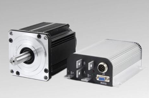
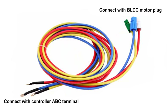
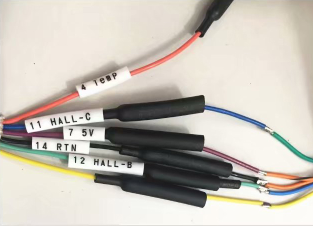
There are three leads for the BLDC motor and five Hall leads. The eight leads must be corresponding to the lead of the controller. Otherwise, the electric motor cannot move normally.

Generally, the brushless DC motor with the phase angle of 60°and 120°requires the brushless DC motor controller of the 60°and 120°phase angle for driving. The controller of these two phase angles requires no direct exchange. There are two correct wirings for the eight leads connecting the brushless electric motor with the phase angle of 60°and the controller with the phase angle of 60°. One is forward rotation and the other is backward rotation.
As to the BLDC motor with the phase angle of 120°, by adjusting the phase sequence of the coil lead and the phase sequence of the Hall lead, there are six correct wiring methods for eight wires connecting the electric motor and the controller. Among them, three wiring methods adopt the forward rotation of the electric motor, while the other three wiring methods adopt the backward rotation of the electric motor.
If the brushless DC motor has no inversion, it means the phase angle between the brushless controller and the brushless DC motor is matched with each other. In this way, we can control the switching direction of the electric motor. The Hall lead A and C of the brushless electric motor and the controller are exchanged for wiring.

The intelligent brushless DC motor controller has appeared on the current market. The intelligent brushless controller has the function of automatically recognizing the electric motor’s phase angle, and can realize the controller for the brushless DC motor at the phase angle of 60°and 120°, respectively. During installation of the controller, the connectors connected with the controller must be placed vertically to the ground so as to prevent ponding of connectors. Use the nylon bondage to fix the controller’s lead onto the vehicle to prevent the friction between the lead and the vehicle body to damage the lead. The controller should be installed at a position which is away from the ground as far as possible. Besides, the opening of the controller shell should be downwards to prevent water from coming into the controller.
Next, this video will show you how to wire ATO high torque BLDC motor with the motor controller.

The BLDC motor includes the stator and the rotor. The stator includes the iron core and the coil winding. The iron core includes the yoke of the centric hole and the gear part evenly distributed in the peripheral of the yoke. The gear part is externally set up with the teeth top. The coil winding includes the wire wrapping package on every gear part. Between every two adjacent gear parts, there should be a notch which can tolerate the coil packet. After the coil winding is connected with the electricity, an independent magnetic line is formed above the top of every gear top, which mutually collaborates with the magnetic elements of the internal ring of the rotor to drive the rotating of the BLDC motor.

Generally, the brushless DC motor with the phase angle of 60°and 120°requires the brushless DC motor controller of the 60°and 120°phase angle for driving. The controller of these two phase angles requires no direct exchange. There are two correct wirings for the eight leads connecting the brushless electric motor with the phase angle of 60°and the controller with the phase angle of 60°. One is forward rotation and the other is backward rotation.
As to the BLDC motor with the phase angle of 120°, by adjusting the phase sequence of the coil lead and the phase sequence of the Hall lead, there are six correct wiring methods for eight wires connecting the electric motor and the controller. Among them, three wiring methods adopt the forward rotation of the electric motor, while the other three wiring methods adopt the backward rotation of the electric motor.
If the brushless DC motor has no inversion, it means the phase angle between the brushless controller and the brushless DC motor is matched with each other. In this way, we can control the switching direction of the electric motor. The Hall lead A and C of the brushless electric motor and the controller are exchanged for wiring.

The intelligent brushless DC motor controller has appeared on the current market. The intelligent brushless controller has the function of automatically recognizing the electric motor’s phase angle, and can realize the controller for the brushless DC motor at the phase angle of 60°and 120°, respectively. During installation of the controller, the connectors connected with the controller must be placed vertically to the ground so as to prevent ponding of connectors. Use the nylon bondage to fix the controller’s lead onto the vehicle to prevent the friction between the lead and the vehicle body to damage the lead. The controller should be installed at a position which is away from the ground as far as possible. Besides, the opening of the controller shell should be downwards to prevent water from coming into the controller.
Next, this video will show you how to wire ATO high torque BLDC motor with the motor controller.
Post a Comment:
You may also like:

