Category

BLDC Motor Supplier
Home » BLDC Motor Wiki » What is a Brushless DC Motor Construction?
What is a Brushless DC Motor Construction?
The brushless DC (BLDC) motor is a type of the synchronous electric motor. In other words, the rotating speed of the electric motor's rotor is subject to the impact of the speed of the stator's rotating magnetic field and the number of the stator's poles (p), namely n=60.f/p. When the number of the stator's poles is fixed, change of the frequency of the stator's rotating magnetic field can change the rotating speed of the stator.
Stator
The BLDC motor stator is composed of many silicon steel sheets through overlying and axial stamping. Within every stamping notch, certain number of coils form the winding. See the figure below. The BLDC motor's stator is similar to the induction machine's stator but is different from the distribution of the stator winding. Most BLDC stators have three windings which are aligned in the shape of star. Every winding is made up of many internal steel plates, which are composed in some way. The even number of windings is distributed in the surrounding of stators to form the even number of magnetic poles.

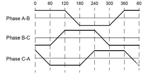
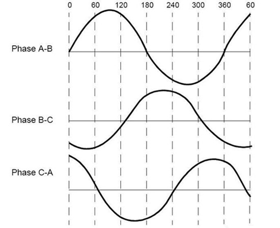
The stator winding of the BLDC motor can be divided into the trapezoid winding and the sine winding. Their fundamental difference is that different connection methods of the winding can lead to differences of their back electromotive force, which can be divided into the trapezoid waveform and the sine waveform. The back electromotive waveform generated by the trapezoid and sine winding is shown below.


Besides, the winding of the back electromotive force is different. Its phase current is also in the trapezoid waveform and the sine waveform. It can be imagined that, since the waveform is smooth, the sine winding, when being operated, is steadier than the trapezoid winding. However, the sine winding has more windings, so that it needs more copper wire than the trapezoid winding.
Rotor
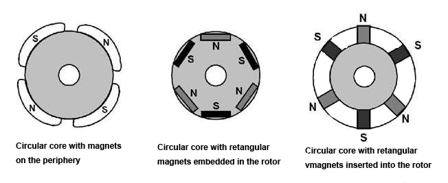
The brushless DC motor's rotor can be divided into the internal rotor rotation and the external rotor rotation. Two to eight pairs of permanent magnets constitute the internal rotors nearby the rotor according to alternative alignment of the N pole and the S pole. When the permanent magnet is pasted within the wall of the rotor, it is the BLDC motor with an external rotor. See below.

Note: The Hall elements' voltage ranges from 4V to 24V, and the current ranges from 5mA to 15mA. Therefore, in choosing the motor controller, we should consider the current and voltage requirements of Hall elements. Besides, the Hall elements output the collector open circuit, which, when used, should be connected with the pull-up resistor.
Stator
The BLDC motor stator is composed of many silicon steel sheets through overlying and axial stamping. Within every stamping notch, certain number of coils form the winding. See the figure below. The BLDC motor's stator is similar to the induction machine's stator but is different from the distribution of the stator winding. Most BLDC stators have three windings which are aligned in the shape of star. Every winding is made up of many internal steel plates, which are composed in some way. The even number of windings is distributed in the surrounding of stators to form the even number of magnetic poles.

The stator winding of the BLDC motor can be divided into the trapezoid winding and the sine winding. Their fundamental difference is that different connection methods of the winding can lead to differences of their back electromotive force, which can be divided into the trapezoid waveform and the sine waveform. The back electromotive waveform generated by the trapezoid and sine winding is shown below.


Rotor
The brushless DC motor's rotor can be divided into the internal rotor rotation and the external rotor rotation. Two to eight pairs of permanent magnets constitute the internal rotors nearby the rotor according to alternative alignment of the N pole and the S pole. When the permanent magnet is pasted within the wall of the rotor, it is the BLDC motor with an external rotor. See below.

Hall sensor
Different from the brush DC electric motor, the brushless DC motor adopts the electronic commutation. The rotor should be electrified according to certain sequence so as to rotate the motor. Then, it is necessary for us to know the position of the rotor for our convenience of electrifying the stator coil according to certain electrification sequence. The stator's position perceived by the Hall sensor embedded in the stator. Generally, three Hall sensors are arranged nearby the rotating path. Under any condition, as long as the rotor's magnetic poles, the current magnetic poles of the rotor will output the corresponding level, either high or low. In this way, we just need the sequence of the electric level generated by three Hall elements to judge the current position of the rotor and electrify the corresponding stator winding.Note: The Hall elements' voltage ranges from 4V to 24V, and the current ranges from 5mA to 15mA. Therefore, in choosing the motor controller, we should consider the current and voltage requirements of Hall elements. Besides, the Hall elements output the collector open circuit, which, when used, should be connected with the pull-up resistor.
Post a Comment:
You may also like:

